Launch evidence guides
Why Elevated Plumes Can Appear in the Wrong Place on a Map
Published (UTC)
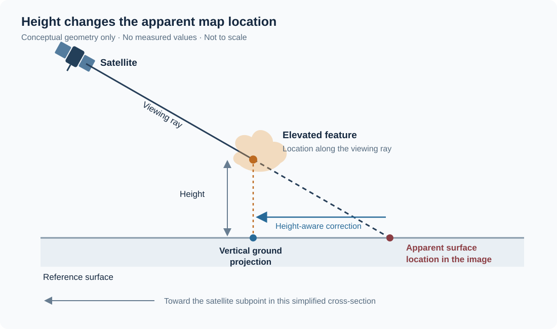
A plume can appear offshore, downrange or beside a launch site even when the map projection is working as designed. The image may place radiation from an elevated feature at the surface point farther along the satellite's line of sight. That apparent displacement is parallax.
Before drawing a path from a bright feature to a map marker, ask what the coordinates represent. A launch-site coordinate, a surface-referenced image pixel and the horizontal position beneath an elevated plume are different quantities. A convincing overlay can conceal those differences.
A published example with a measurable map consequence
In a 2023 study, Bernal Ayala and colleagues examined parallax in GOES ABI data, including a September 7, 2021 Illinois hailstorm. They compared satellite cloud features with radar and surface reports. Using retrieved cloud-top heights, they calculated adjustments of about 14 km for two cloud cores. Their comparison also showed that assuming one maximum height and using varying pixel heights need not produce the same result.
Those are the paper's cloud results, not measurements of a rocket plume. They show why height and viewing geometry deserve attention before images and surface reports are compared. They do not provide a correction distance that can be copied to another event.
Follow the viewing ray
The NOAA Enterprise Cloud Height algorithm document explains that apparent displacement increases with feature height and oblique viewing geometry. Imagine extending a ray from the satellite through an elevated feature until it reaches the assumed surface. A surface-referenced image assigns the ray to that intersection. The point directly below the feature is closer to the satellite's subpoint, the location on Earth directly beneath the spacecraft.
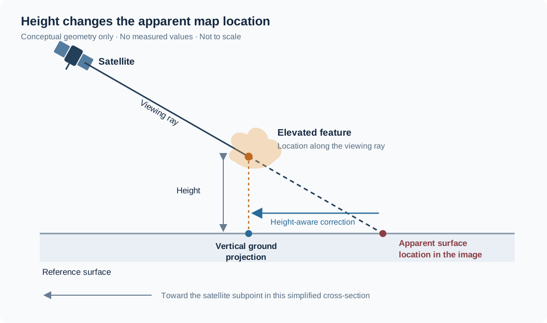
In the simplified local flat-surface picture, the displacement is approximately height above the reference surface multiplied by the tangent of the viewing angle from the local vertical. This explains the trend: a higher feature or a more oblique view can produce a larger offset. It is a teaching approximation, not a substitute for a geolocation algorithm on a curved Earth, especially near the limb.
For the geostationary surface-mapping case described here, the apparent location is displaced away from the satellite subpoint, and correcting an elevated feature moves its inferred ground projection toward that subpoint. This is not necessarily north, south or downrange on your map. Direction depends on the event's location relative to the satellite.
Height is an input with its own uncertainty
EUMETSAT's parallax correction resources describe height-dependent mappings between image locations and inferred cloud positions. The legacy resource page warns that its supplied code has reported errors; it is cited here for the geometric idea, not as a verified implementation. Its 3MI co-registration explanation likewise describes using terrain, cloud-top or scattering-layer height in line-of-sight geometry. The common lesson is that a correction must be tied to the height of the feature being located.
That becomes difficult for an evolving plume. An emitting or scattering feature can extend through a range of heights. A visible cloud edge and the strongest signal in another band may not identify the same part of that structure. A meteorological cloud-top product should not be assumed to retrieve the relevant height of hot exhaust without evidence that its assumptions are appropriate.
If the height is unknown, preserve that unknown. A clearly labeled range of assumed heights can support a sensitivity illustration: show how the inferred location changes across that range. It cannot establish which height was correct. Never infer the height merely by shifting the image until it agrees with the launch-site marker.
A location review you can repeat
- Identify the displayed coordinates. Save the source file, spacecraft, band, acquisition interval and navigation metadata. Determine whether the product is referenced to an ellipsoid, terrain or a height-adjusted layer, and whether any correction has already been applied.
- Check timing and feature identity. Two images taken at different times can show real motion. Two bands can emphasize different parts of a scene. Confirm that the feature being compared is plausibly the same feature before interpreting an offset geometrically.
- State the height evidence. Name the retrieval or independent measurement, its time, vertical reference and uncertainty. If only an assumed interval is available, label every resulting location as conditional on it.
- Preserve the original and corrected layers. Record the algorithm, version, Earth model, projection and resampling. Avoid applying a second correction to an already corrected product.
- Report a bounded conclusion. Distinguish the original surface-referenced position, a height-conditional ground projection and any separate model of the vehicle. Keep uncertainty visible at the scale of the map.
The workflow also applies beyond GOES. NASA's VIIRS VNP03IMG geolocation product uses spacecraft geometry, an Earth ellipsoid, geoid and terrain information, and provides viewing angles and quality flags. Terrain correction locates the terrain surface; it does not, by itself, supply the height of a plume above it. Use the navigation definition for the actual product rather than assuming that every latitude-longitude array represents the feature you want.
Other offsets can look similar
Parallax is one candidate explanation. An apparent mismatch can also involve true transport, inconsistent timestamps, navigation uncertainty, geolocation pairing errors or a resampled display. An image can contain more than one of these effects. A larger offset is not automatically stronger evidence of parallax.
Similarly, a sequence of surface-mapped points from a rising feature can combine horizontal motion with changing height-dependent displacement. Joining those points with a line does not produce a measured three-dimensional trajectory. Two viewpoints can add geometric information, but they still require appropriate timing, navigation and identification of corresponding features; simply overlaying two pictures is insufficient.
Keep the map label honest
Use LaunchDetect's USSF-385 evidence page to practice reading the distinction between imagery and modeled object paths. The LaunchDetect API guide states that snippet coordinates identify the launch site. They are not plume-pixel coordinates or impact locations. In a map application, label such a point as a launch site rather than moving an observed feature onto it.
A useful caption might say: “Surface-referenced image location; elevated-feature position has not been corrected for height.” If a documented correction is available, identify its height source and uncertainty beside it. That small piece of context can prevent a precise-looking map from making a claim the data never measured.
Sources and further reading
Source pages checked October 3, 2026. Historical documents retain their stated version and event dates.
- Bernal Ayala et al. 2023 Parallax Shift in GOES ABI Data [P001]
- NOAA Enterprise Cloud Height ATBD, v3.4 September 2020 [P002]
- EUMETSAT Convection Working Group parallax corrections [E001]
- EUMETSAT 3MI co-registration and height-aware geometry [E002]
- NASA VNP03IMG geolocation product [N006]
- LaunchDetect public detection API guide [LD002]
- LaunchDetect USSF-385 public evidence record [LD003]